Introduction
Working on a customer project making use of an Espressif ESP32 microcontroller we bumped into a known yet not all that well publicised hardware bug involving its GPIO interrupt implementation.
The customer’s product features two SPI connected peripherals. Each making use of an interrupt to inform the host when new data is available for collection.
We found that very occasionally one of these peripherals would lock up. The peripheral in this case was an inertial measurement unit (IMU). The IMU was configured to generate an interrupt when its internal sample queue reached a certain sample count.
After a little…ok lot of head scratching it was eventually found that the IMU was going its job. It generated its interrupt as expected and waited to be queried by the host, a query which would never come as the ESP32 had seemingly lost or ignored the interrupt for some reason.
It wasn’t immediately clear why the IMU would lockup in this case, however it was later discovered that the IMU would stop generating interrupts until the samples in the buffer were collected by the host.
Reproduction
Having found that the IMU was keeping up its end of the bargain and a thorough code review yielding no software suspects, the hardware itself became suspect.
Reproduction with the customer’s hardware was problematic. The system would sometimes run for hours without issue, other times only minutes.
Starting to suspect an issue with interrupt handling, I had the idea of configuring a signal generator to produce a series of interrupts, to see how the ESP32 behaved.
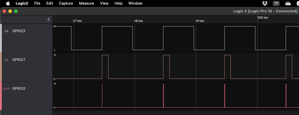
Providing 1Khz square waves on GPIO23 and GPIO27 (the lines used in the customer’s product), synchronised but delayed with respect to one another.
In the interrupt handlers, the lower numbered GPIO23’s handler, would set a GPIO line high. The higher numbered GPIO27’s handler would set the same GPIO line low (I may have had a peek into the interrupt handling code in selecting this arrangement).
The expected behaviour is therefore short pulses on the GPIO line, between the interrupts. Similar to the following:

The high time of the signals being deliberately different to more accurately represent the real peripherals which were experiencing the issue.
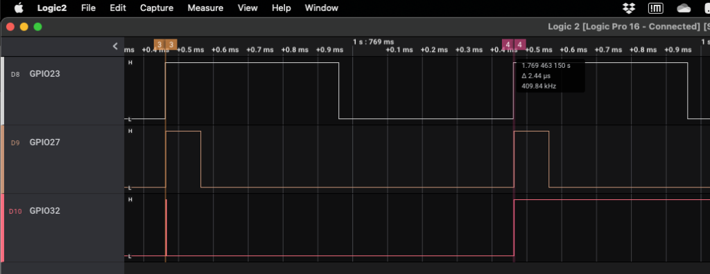
It was found that if the delay between the interrupts was varied by the signal generator the following could be seen when zooming out on the signals:

With the delay configured just right, there are periods where the second interrupt begins to be missed (indicated by the GPIO line remaining high).
The “sweet spot” on this particular device appears to be 2.44uS.

In the capture above marker 3 with a delay of 2.41uS is handled correctly, where as marker 4 with a delay of 2.44uS is consistently missed. Increasing the delay further to 2.46uS resolves the issue and both interrupts are once again seen.
Resolution
Having found what appeared to be a genuine hardware problem, I turned to the scrolls, or Errata documents at least. At the time such a document wasn’t to be found. Either that or my Google foo wasn’t strong enough to find it.
I raised an issue against their SDK in GitHub to which one of their engineers very quickly responded and pointed me at the known issue.
It turned out that rather than searching for “ESP32 Errata” at the time, I should have been searching for “ESP32 Eco and Workarounds”. I guess that’s sort of similar, it has workaround in the name, thats what I was looking for after all. I’ll let them off, hardware is….well….hard 😀.
It would have been nice for the SDK documentation to mention, even in passing, not to use more than one edge triggered interrupt, it wont work but sadly no.
The workaround described in the errata sadly didn’t make all that much sense, but the info provided by the Espressif engineer hinted at what was going on.
Let me give you some more information about this bug: At the clock when the GPIO_STATUS_W1TS_REG or GPIO_STATUS_W1TC_REG is being operated, the GPIO status of the whole 32-bit register cannot be updated. Therefore, the edge-triggered interrupt will be lost if the GPIO interrupt is sampled at the same time of an interrupt status clear operation. And this is what I believe have happened at the “sweet spot” moment!
@songruo via GitHub Issue
It seems that I’d bumped into a race condition involving the acknowledging of the first interrupt and possibly the arrival of the second.
The solution I came up with was based on the last time I found a microcontroller with a fault not dissimilar to this one.
Rather than rely on edge triggered interrupts, which could be missed due to the race condition. Switch to level triggered interrupts, which won’t be missed and infer the edges based on the levels. For example when looking for a falling edge. If a low level is seen the falling edge must have just occurred. Therefore service the interrupt and reconfigure the hardware to interrupt on a high level. When the high level interrupt occurs a rising edge must have just passed, in which case ignore it and reconfigure the hardware for a low level again.
Handing twice as many interrupts as required, and having to keep additional book keeping information but….it does work.
Here’s my header only workaround for Espressif’s ESP-IDF framework:
#ifndef GPIO_ISR_WORKAROUND_H
#define GPIO_ISR_WORKAROUND_H

/*
** ESP32 GPIO interrupts don't work properly for edge triggering.
** See section 3.14 of ECO and Workarounds document: https://www.espressif.com/sites/default/files/documentation/eco_and_workarounds_for_bugs_in_esp32_en.pdf
*/

/* Standard libraries */
#include <stdint.h>

/* ESP32 */
#include "driver/gpio.h"

/* GPIO state */
typedef struct
{
    /* GPIO number */
    uint32_t uiGPIONum;

    /* Rising edge trigger? (otherwise falling edge) */
    bool bRisingEdge;

    /* Trigger level met (high in case of rising edge, low in case of falling edge) */
    bool bTriggered;

} stGPIO_ISR_WORKAROUND_State_t;

static inline void GPIO_ISR_WORKAROUND_InitAndEnableISR(stGPIO_ISR_WORKAROUND_State_t *pstState, uint32_t uiGPIONum, bool bRisingEdge)
{
    /* GPIO number */
    pstState->uiGPIONum = uiGPIONum;

    /* Rising edge trigger? (otherwise falling edge) */
    pstState->bRisingEdge = bRisingEdge;

    /* Trigger level not yet met */
    pstState->bTriggered = false;

    /* Set first level */
    gpio_set_intr_type(uiGPIONum, bRisingEdge ? GPIO_INTR_HIGH_LEVEL : GPIO_INTR_LOW_LEVEL);

    /* Enable interrupt */
    gpio_intr_enable(uiGPIONum);
}

static inline bool GPIO_ISR_WORKAROUND_Process(stGPIO_ISR_WORKAROUND_State_t *pstState)
{
    if (pstState->bTriggered)
    {
        /* Second callback, having triggered, start monitoring for opposite level */
        gpio_set_intr_type(pstState->uiGPIONum, pstState->bRisingEdge ? GPIO_INTR_HIGH_LEVEL : GPIO_INTR_LOW_LEVEL);
    }
    else
    {
        /* First callback, edge has arrived, start monitoring for opposite edge */
        gpio_set_intr_type(pstState->uiGPIONum, pstState->bRisingEdge ? GPIO_INTR_LOW_LEVEL : GPIO_INTR_HIGH_LEVEL);
    }

    /* Toggle triggered */
    pstState->bTriggered = !pstState->bTriggered;

    return pstState->bTriggered;
}

#endif
An example usage would be as follows:
static stGPIO_ISR_WORKAROUND_State_t eISRState

void SetupInterrupt()
{
	gpio_isr_handler_add(INTERRUPT_PIN_NUMBER, ExampleInterruptHandler, NULL);
	GPIO_ISR_WORKAROUND_InitAndEnableISR(&eISRState, INTERRUPT_PIN_NUMBER, false);
}

static void IRAM_ATTR ExampleInterruptHandler(void* pvArg)
{
	if (!GPIO_ISR_WORKAROUND_Process(&eISRState))
	{
		/* Workaround says interrupt hasn't really triggered */
		return;
	}

	/* Handle interrupt as required */
}
With the above workaround in place, the signal generator sweep test now passes regardless of the delay between interrupts. Integrated into the customer’s product the IMU lockup issue hasn’t been seen since 😊.

Leave a Reply